Part 1: Cloud Foundation on VxRail-Understanding NSX-T Deployment in the Management Domain
- Martin Hayes

- Feb 27, 2022
- 6 min read
So, you have successfully gone through the ‘Bringup’ for the Cloud Foundation Management domain. At the time, there wasn’t a business or operational requirement to deploy NSX-T Application Virtual Networks (AVN’s), but circumstances have changed in the interim. Perhaps you require AVN’s to support a vRealize solution or your environment has grown, and you need to add multi-site capability (DR or Active-Active). Of course, you may wish to leverage all the other benefits of NSX-T to support workload security, networking and automation use cases related to traditional and emerging containerized workloads. (A future blogpost will explore some of these in a bit more depth)
Thankfully, Cloud Foundation on VxRail, has a built-in ‘Day 2’ workflow that allows us to deploy a fully featured NSX-T environment to support these use cases. This removes much of the heavy lifting, as SDDC Manager automates virtually all of the configuration. The workflow logic, in order to be succesful however, does assume that you understand how the NSX-T Edge cluster is constructed and how the environment will interface with the physical network (eBGP, Route Injection, Failover etc). The purpose of this series of posts is to aid this understanding and hopefully help our users get the most out of of the rich feature set and capability of VCF on VxRail.
As the title suggests this post is split into two parts. Part 1, (this post) concentrates on understanding how the workflow is constructed and what it delivers. Yep, the the theory! Note: A base level knowledge of Cloud Foundation & VxRail and its associated terminology is a requirement.
Part 2 (published at the same time) provides a video demonstration of what we have configured. I'm sure everybody will be tempted to skip straight to the video, but trust me the demo will make much more sense if reviewed in tandem.
Post initial ‘Bringup’ – What has been deployed?
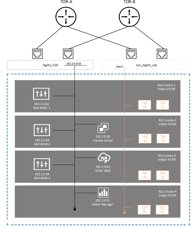
CloudBuilder does of course deploy the base NSX-T components in the Management domain, regardless of whether you have chosen to deploy AVN’s or not. We aren’t starting from scratch! The NSX-T Management/Control cluster is deployed (3 X Managers), and hosts in the management domain are configured or ‘prepped’ with NSX-T kernel VIBs and software. Each host is also configured with TEPS (Tunnel Endpoints). We end up with a steady state configuration representative of Figure 1 below:
In this example we are using a 4 NIC configuration using VCF on VxRail ‘Profile 3’ which dedicates vmnic0, vmnic1 to the primary vDS (Created by VxRail Manager) and vmnic2, vmnic3 to the secondary vDS (Created by CloudBuilder).

Figure 1 would be very typical of a 4 Node Management domain topology. CloudBuilder has looked after the deployment of the NSX-T managers and configured some DRS anti-affinity rules, to ensure we avoid co-hosting managers on the same host. Hosts have also been added to an ‘Overlay Transport’ zone, which means they have been ‘prepped and TEPPED’ – the TEP address here being pulled from a local DHCP server.
Running the Day 2 Workflow
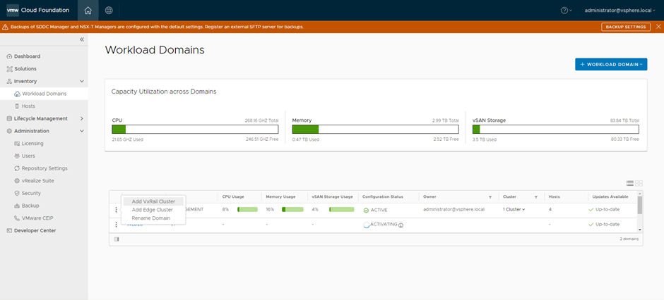
Running the workflow is a very straightforward process. From the Home Screen in SDDC Manager. Toggle the ‘3 Dots’ beside the Management workload domain and select ‘Add Edge Cluster’

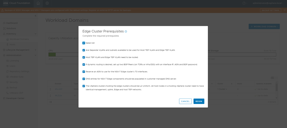
From here we are presented with another checkbox menu, where we are asked to complete Edge Cluster Prerequisites before we can proceed further. This is where we need to begin to understand what the desired outcome will look like. In most scenarios we will want to run a dynamic routing protocol such as BGP to manage dynamic failover and automatically inject AVN address space into the routing table upon creation. We ‘Select All’ to continue.

Next, we are presented with an imperatively driven set of menus that require us to input a series of variables to successfully deploy a validated Edge Cluster. At this point we need to take a step back to understand what the workflow will configure on our behalf. This is where we really need to dig into understanding the design. At this point, I will shy away from delivering more screengrabs of the workflow, the video demo will provide more than enough in this regard.
Understanding the Workflow Design and Outcome
As mentioned, the workflow really does take much of the heavy lift away, especially for those not innately familiar with NSX-T and its associated configuration semantics. Nonetheless, we do need to understand at a high level the routing integration with the TOR switches, the design of the NSX-T Edge Cluster and the interaction between both.
Assuming we wish to deploy a dynamic routing (eBGP) then the workflow will configure and deploy the following:
A minimum of 2 X NSX-T Edge Virtual Machines. There is an option to add more but two is a typical of most designs.
These Edge VM’s are then grouped together into an ‘NSX-T Edge Cluster’. This is not to be confused with a vSphere cluster, but rather it is a construct to manage NSX-T Edge redundancy and scalability.
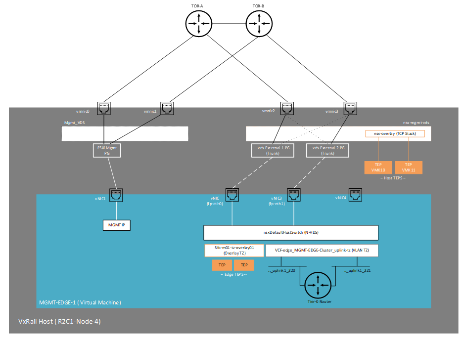
Each Edge Virtual Machine is then configured with VLAN uplinks for BGP peering. One to each TOR switch (as per Figure 4 below). In our design, they are VLAN 220 and 221. These reside on our second unused VDS that we configure during the ‘Bringup’ process (nsx-mgmt-vds)
The workflow then asks you to input the parameters to enable BGP connectivity to the two physical TOR switches, these include source and destination IP addresses for the BGP TCP sessions and the local BGP AS number as well as the remote BGP AS number. Neighbour peering to different AS numbers implies that these sessions are eBGP (External BGP). Note: NSX-T also configures an iBGP session between the two Tier-0 instances, this is done automatically via the workflow, so no user input required here.
The workflow will not configure the corresponding TOR switches. These need to be configured to ‘speak’ BGP with the NSX-T domain. The workflow will however validate the end-to-end configuration and the following must be configured:
BGP AS Domain (In this example 65001)
BGP Neighbor and Remote AS (Autonomous System). These are the NSX-T Edge VM Interfaces and the AS number of the NSX-T environment
An injected route/prefix.
The last requirement is interesting. SDDC Manager will look to validate, once the NSX-T relationship is built with the physical network, that it has successfully learned a route from BGP (technically received a prefix update). In most instances this will be a ‘default – route’, 0.0.0.0/0, indeed this is the specific route SDDC Manager looks to validate. The below example contains a code snippet from a Dell switch running OS10. The configuration on other popular TOR switches such as Cisco and Arista should be broadly similar. Note, this configuration is a snippet only and demonstrates what is required to get the relationship up and running. In a 'real world' environment, it is highly likely that the BGP routing configuration will be more complex.

The net result once all the parameters have been imputed and validation has been completed, will consist of the following:
An NSX-T Edge cluster deployed in the Management domain with 2 X Active Tier-0 Routing instances running on two separate Edge nodes.
These will peer north-south via eBGP with the two Dell switches running OS10. ECMP (Equal Cost Multipathing) will also be enabled to ensure fast failover and the full utilisation of the available bandwidth.
A default route will be advertised from the physical network via BGP. The NSX-T domain will ‘learn’ this prefix and advertise it internally.
A Tier-1 Router will be configured that will connect to the Tier-0 Routers. NSX-T logical switches and AVN’s will connect to this Tier-1 router. BGP will dynamically advertise these networks to the physical network when they are created. This is not represented in the diagram, but we will review in the video portion in part 2.
Cloud Foundation Edge Host Automation
There is quite a bit of variable data that needs to be inputted into the workflow and as outlined above it is important to understand up front what the intended outcome will look like from a logical and physical routing perspective. The real benefit though is SDDC manager automates many of the complex ‘under the hood’ configuration tasks needed to deploy the Edge Nodes themselves. This involves the configuration of the virtual switch dedicated to the NSX-T Underlay/Overlay, the Edge Node uplink profile, Edge TEP deployment, and special configuration of the uplink segments to ensure proper north-south traffic steering. These are non-trivial tasks that the workflow automates on our behalf.
The following diagram (Figure 5) provides some insight into how the Edge-Node VM is configured. Note it is a VM running Ubuntu Linux, configured with 4 virtual network adapters. The first carrying management traffic via the MGMT-DVS and the second and third carrying overlay (TEP) and North-South traffic from the Tier-0 routing instance via the second VDS ‘nsx-mgmt-vds’

Up next Video Demo
In the next post (Part 2) we will take some time to run though this in the lab, starting with a VxRail system that is in a steady state post VCF bringup. In order to make things a little easier to digest and understand, we have used all the same IP addresses and naming conventions as per the diagrams above. You should also be able to expand/copy the diagrams and use in conjunction with the video. Apologies for some of the small font/print, but there is only so much you can fit on a page but the devil is truly in the detail!
Comments